Menu Bar
The menu bar (as shown in Figure 3.2) contains different labels for the different workflows to create and analyse their digital design simulations. Table 3.2 provides a quick description of the different labels available in the LogicPlot menu bar.

Table 3.2: Brief description of different labels available in the LogicPlot simulator menu bar
| Name | Description |
| Project | Lists different workflows for creating, opening and managing LogicPlot simulation files. |
| Circuit | Lists different workflows for creating new circuits and inserting sub-circuits. |
| Tools | Lists different tools available within the simulator for creating and analyzing a circuit simulation. |
| Help | Lists different user assistance resources while using LogicPlot. |
Project
LogicPlot keeps projects on your own machine, either in the browser's local storage or as files. Table 3.3 shares a brief description of the different options available in the Project drop-down menu (refer Figure 3.3).
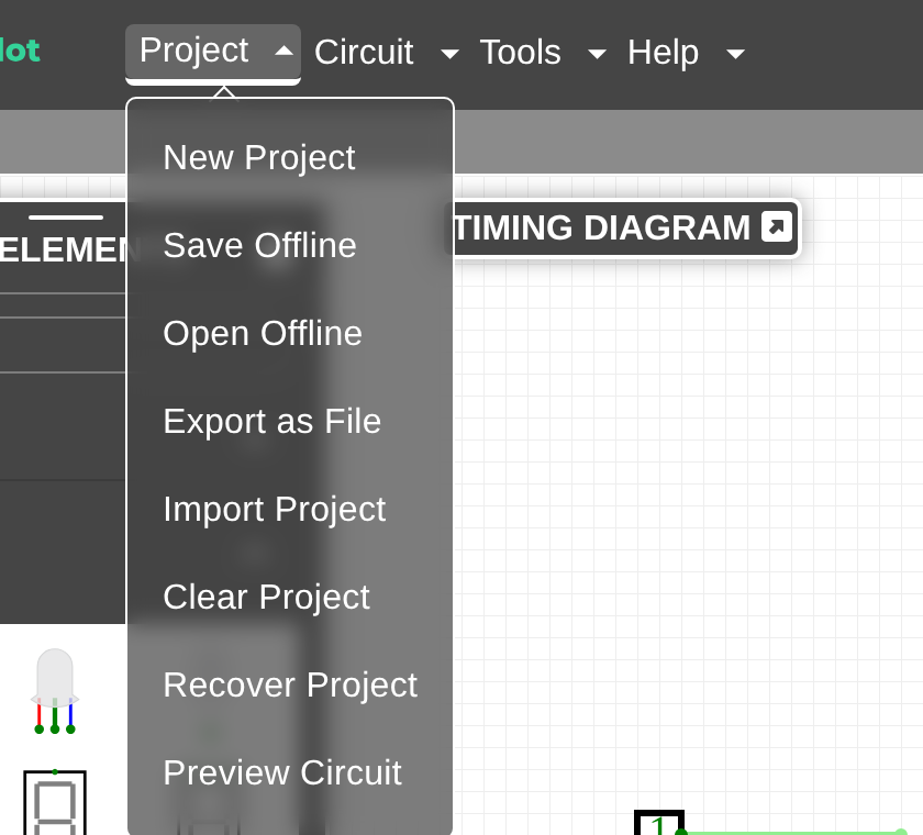
Table 3.3: Brief description of different selections available in the Project drop-down menu
| Name | Description |
| New Project | Opens a new project file for building a live circuit |
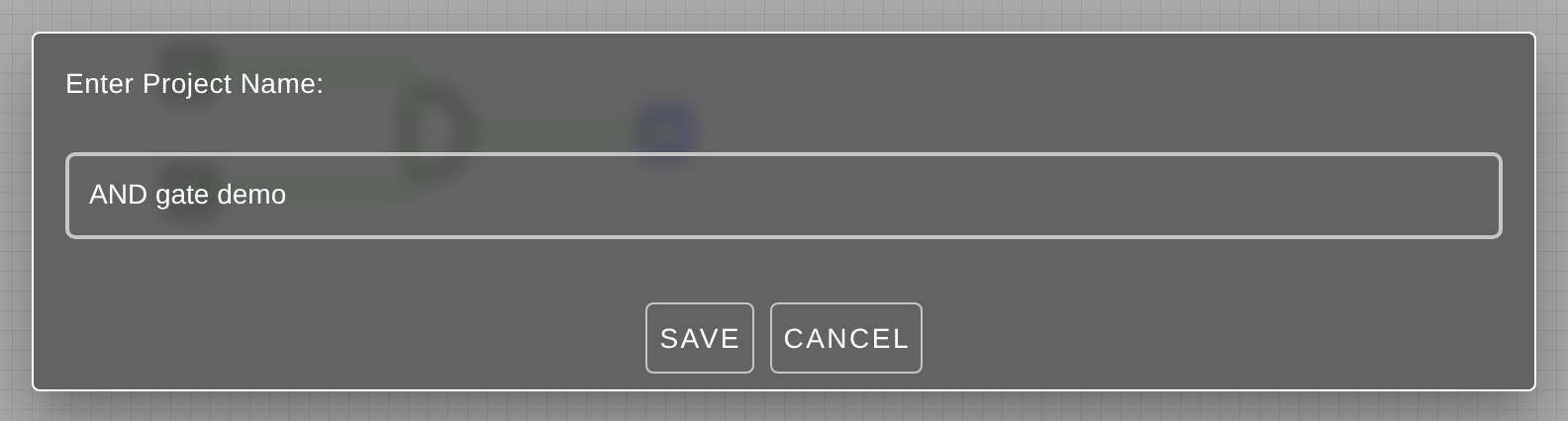
| Save Offline | Saves the displayed project in the browser's local storage under a project name (refer Figure 3.4). |
| Open Offline | Opens a project from the browser's local storage |
| Open Example | Opens one of the example circuits bundled with LogicPlot, from single gates to whole CPUs |
| Share Link | Packs the whole project into a link, with a QR code and an embed snippet, so it can be opened anywhere without an account (refer Sharing and Exporting) |
| Export as File | Downloads the project as a .cv file that can be shared or backed up |
| Import Project | Loads a previously exported .cv file |
| Clear Project | Clears the content (including all the circuit tabs) of the working project file. |
| Recover Project | Recovers the content of the last project that the user was working on. |
| Preview Circuit | Displays the full circuit view of the displayed image. The simulator zooms in or out so that the circuit image fits the entire screen. |
When saving a project, the simulator asks for a project name (refer Figure 3.4). The same name is shown in the menu bar and in the Open Offline list.
Circuit
As the circuit design grows, the Circuit drop-down menu (refer Figure 3.5) lists different options for managing the design structure. Table 3.4 further shares a brief description of the different options.
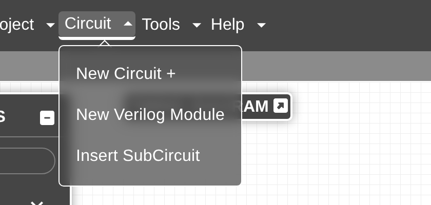
Table 3.4: Brief description of different selections available in the Circuit drop-down menu
| Name | Description |
| New Circuit+ | Adds a new tab in the circuit tab bar |
| New Verilog Module | Inserts a circuit comprising of Verilog module |
| Insert Subcircuit | Inserts a circuit layout generated using LogicPlot simulator as a subcircuit in another circuit tab |
Besides adding multiple circuit tabs within a project, circuit tabs can also be nested within other circuit tabs for organizing a hierarchical design. A subcircuit is a modular functional block that delivers a single function within a given design. Additionally, a subcircuit generated using a Verilog module can also be inserted.
NOTE: Unlike LogicPlot simulations, the circuit generated using a Verilog module can be simulated as a subcircuit only.
Tools
Table 3.5 shares a brief description of the different options available in the Tools drop-down menu (refer Figure 3.6).
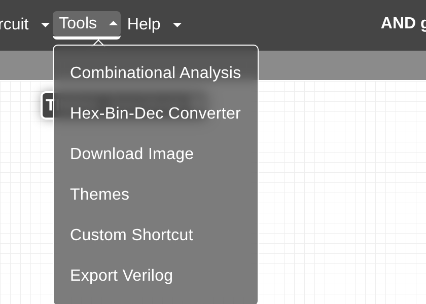
Table 3.5: Brief description of different selections available in the Tools drop-down menu
| Name | Description |
| Combinational Analysis | Converts a truth table data into a circuit |
| Hex-Bin-Dec Converter | Converts a hex number into its equivalent binary and decimal number |
| Download Image | Downloads the displayed circuit design in different formats and resolutions |
| Themes | Displays different colour schemes for defining the aesthetics of the LogicPlot simulator interface |
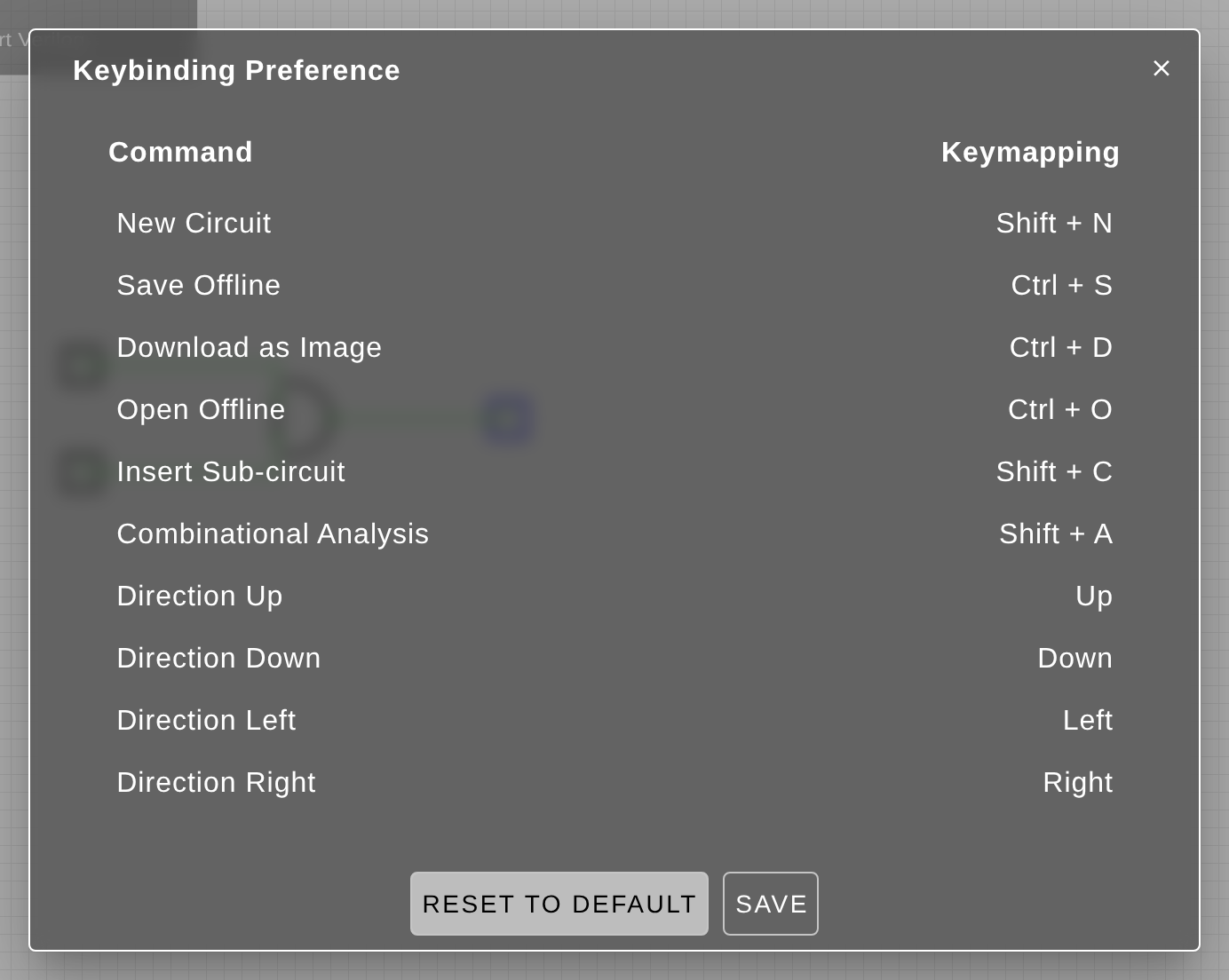
| Custom Shortcut | Displays different keyboard shortcuts for different tasks within LogicPlot simulator |
| Export Verilog | Generates and exports a Verilog file for the displayed circuit design |
Combinational Analysis Tool
The Combinational Analysis tool available within the LogicPlot simulator generates a circuit using combinational analysis or a boolean function (refer Figure 3.7). A truth table is then populated to construct the final circuit using different gates and circuit elements.
NOTE: If the user generates the circuit by entering a boolean function, then the truth table is auto populated else the user must manually set the values.
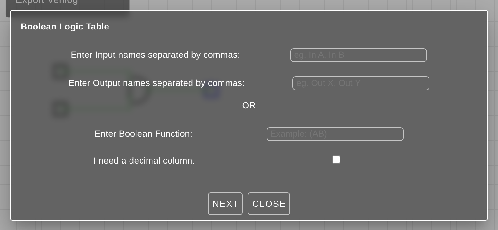
The circuit's inputs and outputs will be displayed in top-down and left-right order corresponding to how they were identified in the Boolean Logic Table popup window.
Hex-Bin-Dec Converter
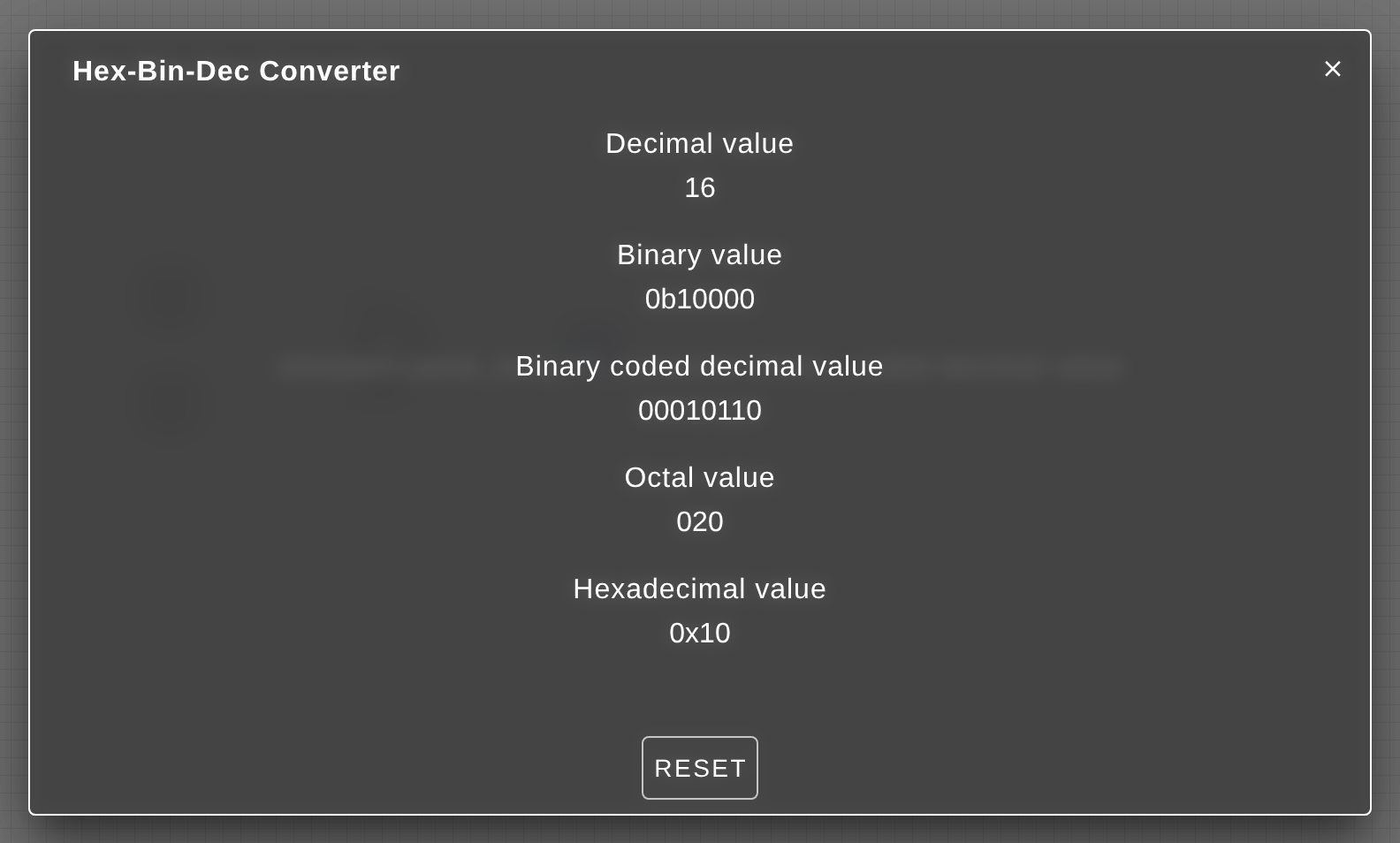
The Hex-Bin-Dec Converter tool (refer Figure 3.8) converts a given binary number into its equivalent decimal, octal or hexadecimal value. Alternatively, a user can also generate a binary value from different available formats.
Themes
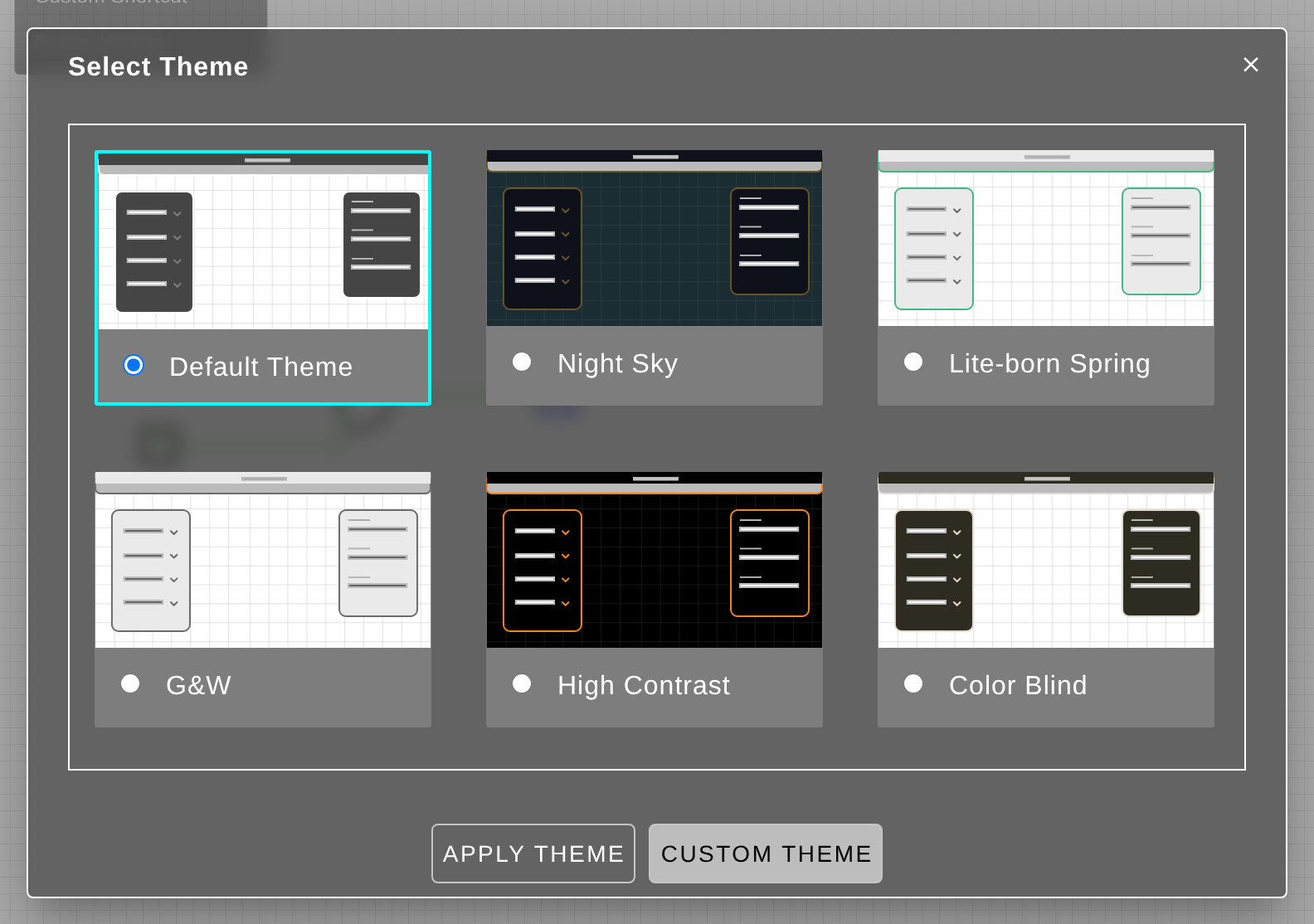
Different themes have been included that change the colors of the LogicPlot simulator user interface (UI) while maintaining the contrast across different UI elements. Refer Figure 3.9.
Custom Shortcuts
The Custom Shortcuts window displays different shortcuts for common user operations. As required, each of the available key shortcuts can be edited for a user preference and restored back to its default value. Refer Figure 3.10.
Export Verilog
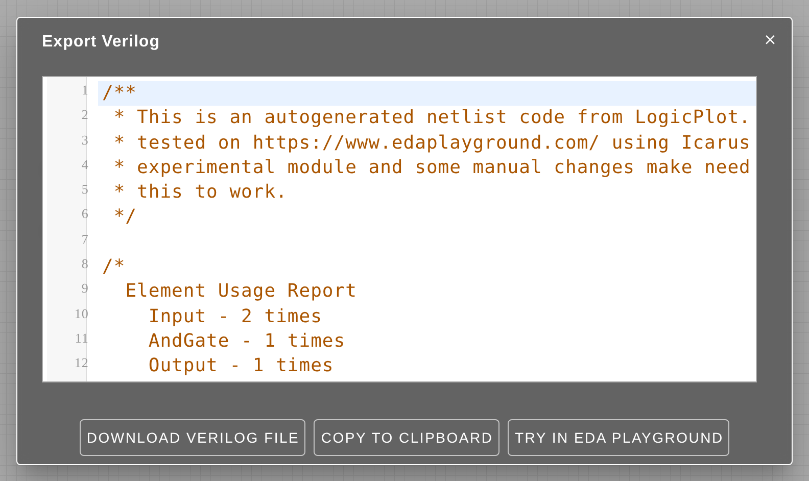
Every circuit simulation project created within LogicPlot can be exported as a Verilog code. As Figure 3.11 illustrates, the code file can then either be downloaded on the machine as a verilog file or tested on https://www.edaplayground.com/ using Icarus Verilog 0.9.7.
NOTE: This is an experimental module and some changes may be needed for the code to work.