Key Features
This section summarises the key features of the LogicPlot simulator.
-
Build and simulate in the browser: Create and run your simulations without installing software or following operating-system-specific instructions. Circuit creation and simulation are seamless, so you can edit and troubleshoot a design while it is running. Projects are saved in the browser's local storage or exported as files.
-
Transform your ideas using a powerful, intuitive and interactive schematic editor:
- Design using an easy-to-use interactive schematic editor: As you drag and drop circuit elements onto the canvas, horizontal and vertical wires can be drawn to complete the connections. Wires are colour-coded so circuits are easy to test and analyse.
- Customise the attributes of circuit elements: LogicPlot includes a large library of circuit elements ranging from basic gates to register-transfer-level components and from basic input/output to system-level parts. Most elements have customisable properties for building complex designs.
- Multi-bit wires (buses): Every input and output element has a bit width. Most elements let you customise the bit widths of their inputs and outputs, and splitters direct individual bits where they need to go.
-
Insert subcircuits: Hierarchical circuits can be created by nesting and reusing smaller circuits inside larger ones.
-
Export images in multiple formats: High-resolution images of your circuits can be exported in several formats, views and resolutions.
-
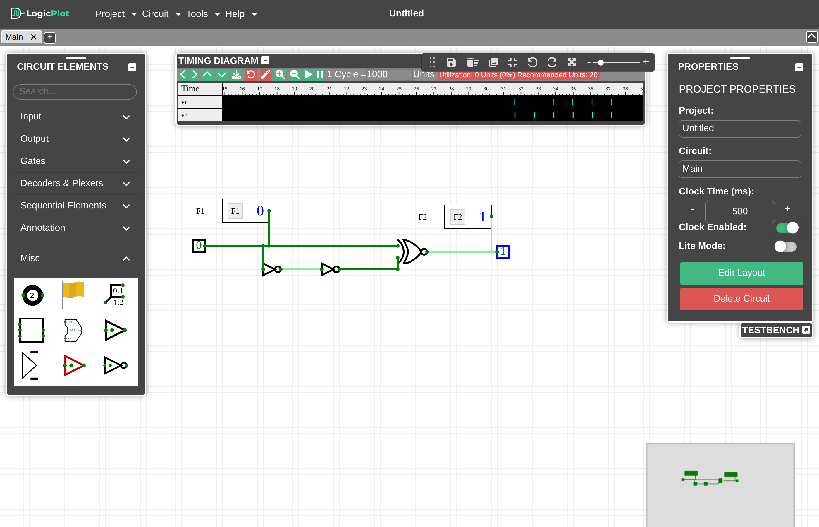
Visualise circuit behaviour using timing diagrams: Timing diagrams help analyse and debug the behaviour of circuits for different input sequences, including logical mistakes and race conditions. Paired with the Flag element they illustrate propagation delay, stable states and race conditions.
-
Test circuits with the testbench: Attach combinational or sequential test vectors to a circuit, run them all at once and see detailed pass/fail results.
-
Work with Verilog: Convert a circuit into Verilog code, or write a Verilog module and insert it as a subcircuit.
-
Share a circuit with a link: Project → Share Link packs the entire project into a URL, complete with a QR code and an
<iframe>snippet for embedding it in a page. Nothing is uploaded: the circuit travels inside the link itself. See Sharing and Exporting. -
Start from an example: Project → Open Example opens one of the circuits bundled with LogicPlot, from a single gate to a complete CPU, so you always have something working to take apart.
-
Runs entirely on your machine: There is no account, no server and no telemetry. Fonts, libraries and the Verilog synthesiser are all bundled, so the simulator keeps working offline once the page has loaded.