Understanding LogicPlot Simulator Interface
Figure 3.1 highlights the different sections of the LogicPlot simulator and Table 3.1 provides a brief description for each section.
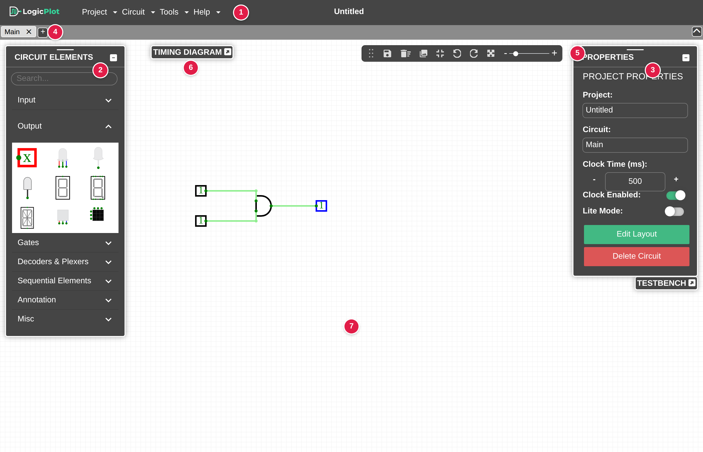
Figure 3.1: Different sections of the LogicPlot simulator
Table 3.1: Different sections of the LogicPlot simulator
| Display Number | Section Name | Description |
| 1 | Menu bar | Displays different options available in the menu bar for managing and creating projects |
| 2 | Circuit Elements Panel | Displays different circuit elements for building the circuit. |
| 3 | Properties Panel | Displays different properties available for the selected circuit element. |
| 4 | Circuit Tabs | Displays different circuits and sub-circuits available within the selected project. |
| 5 | Quick Access Panel | Displays task icons for the common LogicPlot workflows. |
| 6 | Timing Diagram | Displays the level of each input and output after each clock pulse for determining the circuit behavior |
| 7 | Canvas | Display area where the circuit elements can be assembled for building the desired circuit. |
While the CIRCUIT ELEMENTS panel, PROPERTIES panel and the quick access panel can be easily moved around the screen, the CIRCUIT ELEMENTS panel and the PROPERTIES panel are collapsible panels.
Click on the relevant links to learn more about a given section: