Verilog Code to Circuit
LogicPlot allows you to convert Verilog code into a circuit. This feature is useful for those who prefer writing hardware descriptions in Verilog and want to visualize the corresponding circuit by simulating it in LogicPlot Simulator.
Steps to Convert Verilog Code to Circuit
-
Access the Verilog Editor: Navigate to Circuit drop-down menu to select New Verilog Module from the drop down menu. As shown in Figure 8.3, the Enter circuit name pop up window is displayed.
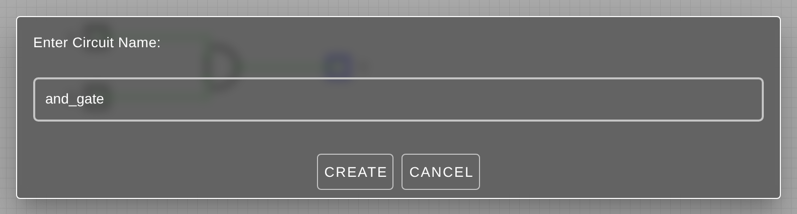 Figure 8.3
 -
Enter a circuit tab name in the text field. Refer Figure 8.3.
-
Click **OK **to launch the Verilog code interface window as shown in Figure 8.4.
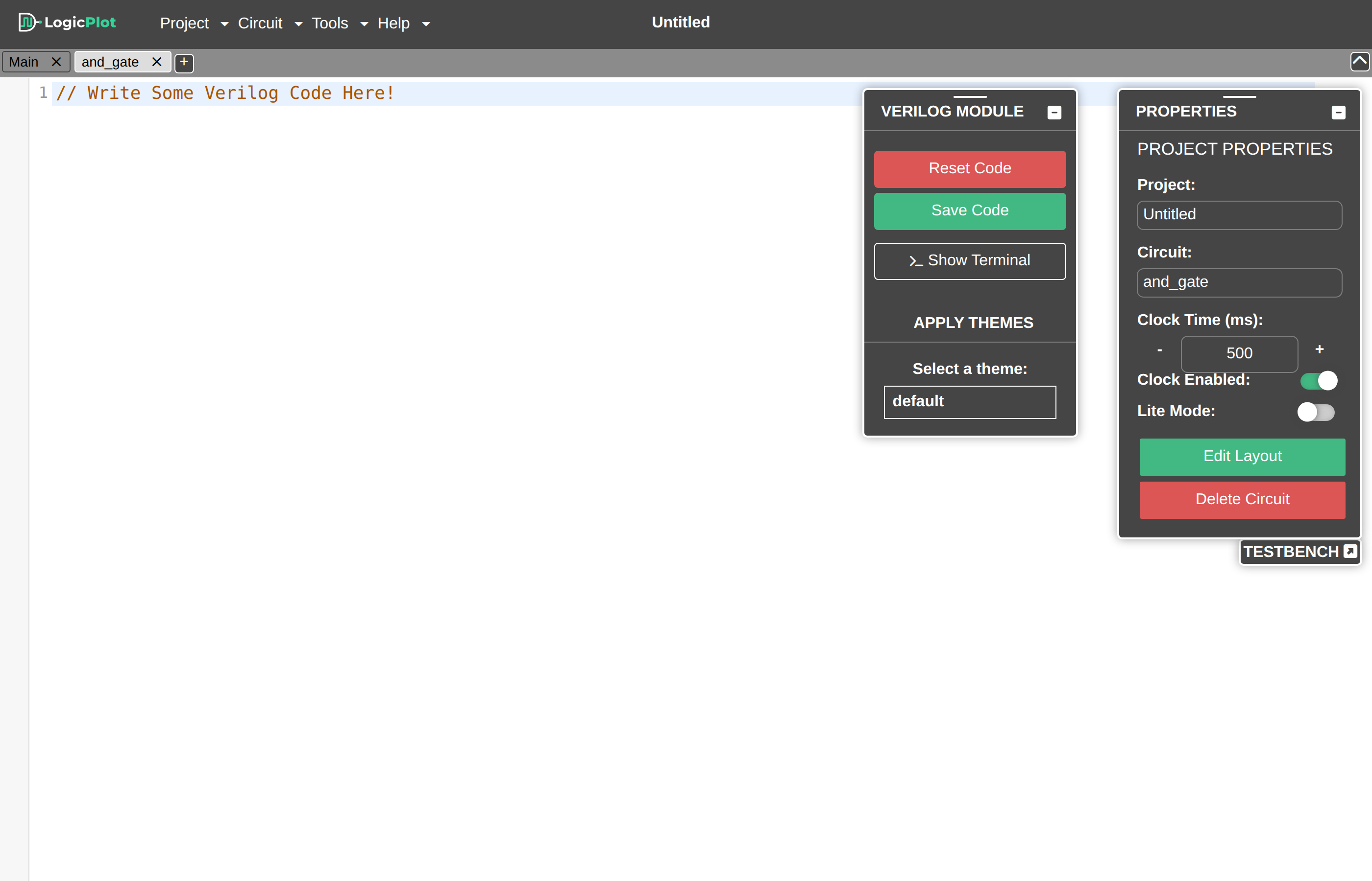 Figure 8.4
 -
Write or Paste Verilog Code: Enter the desired Verilog code in the module interface. Refer Figure 8.5.
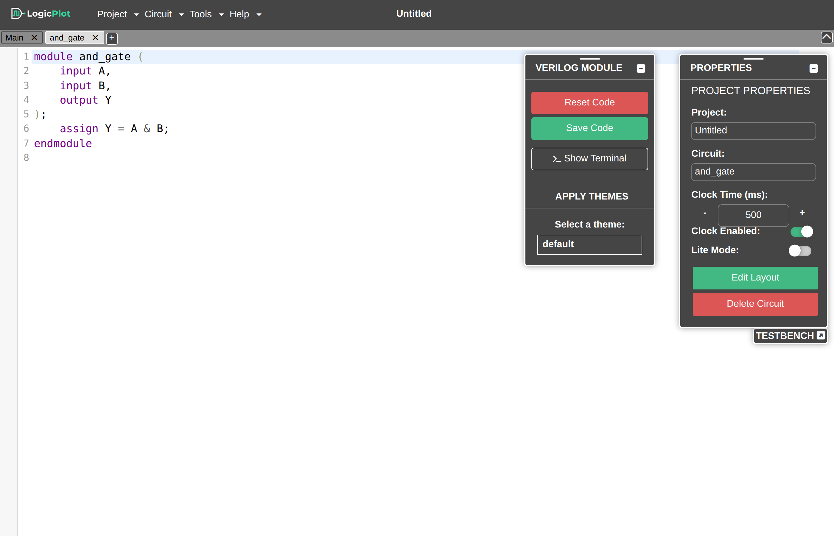 Figure 8.5
 -
Click on the Save Code button to receive the message that the code has been saved successfully. Refer Figure 8.6.
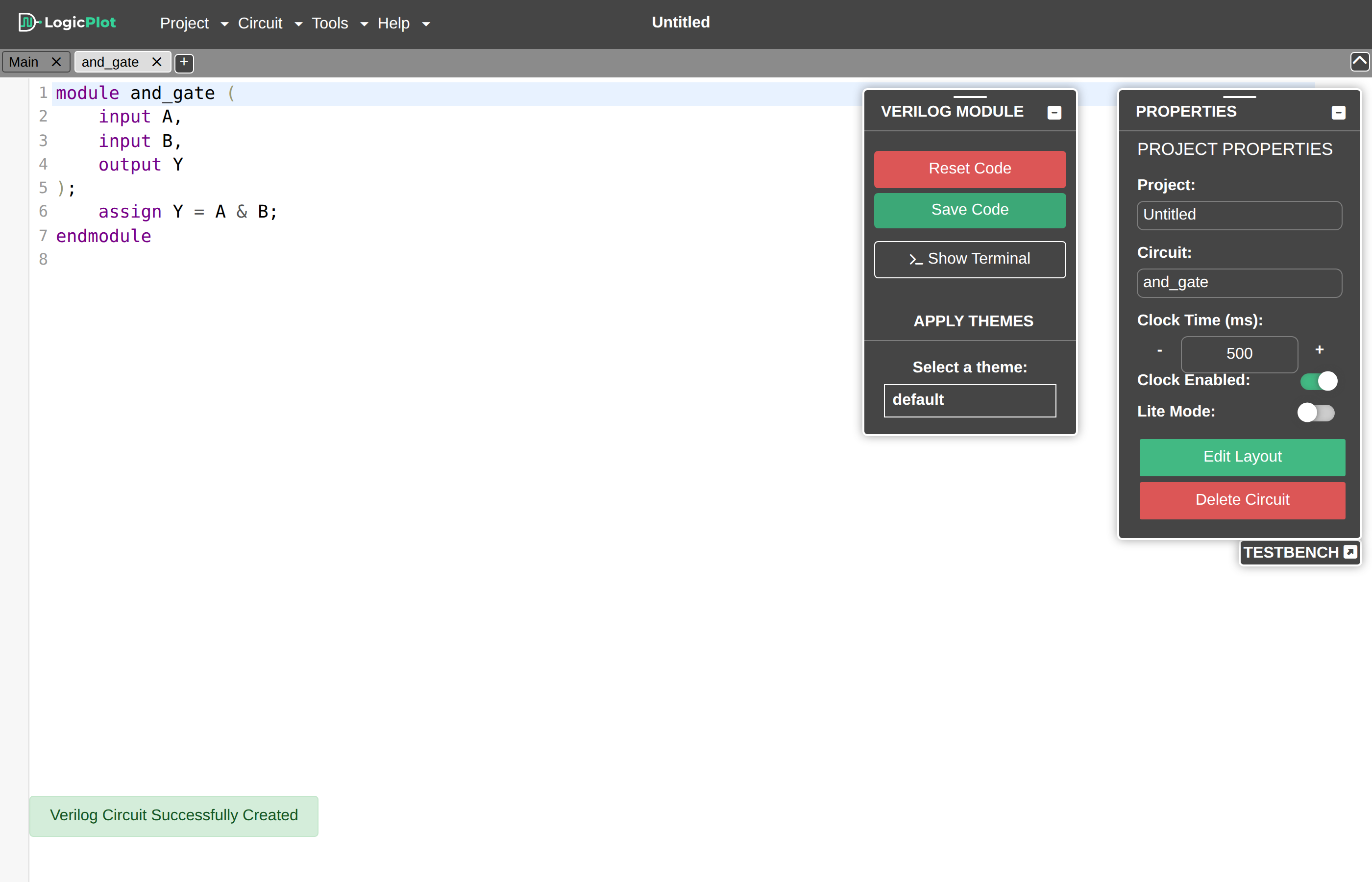 Figure 8.6
 -
Navigate to Simulator back from the Verilog code editor: Refer Figure 8.10
 Figure 8.10
 -
Navigate to Circuit drop-down menu to select Insert SubCircuit from the drop down menu. As shown in Figure 8.7, the Insert SubCircuit pop up window is displayed. Select your Verilog-module name and click on Insert SubCircuit button.
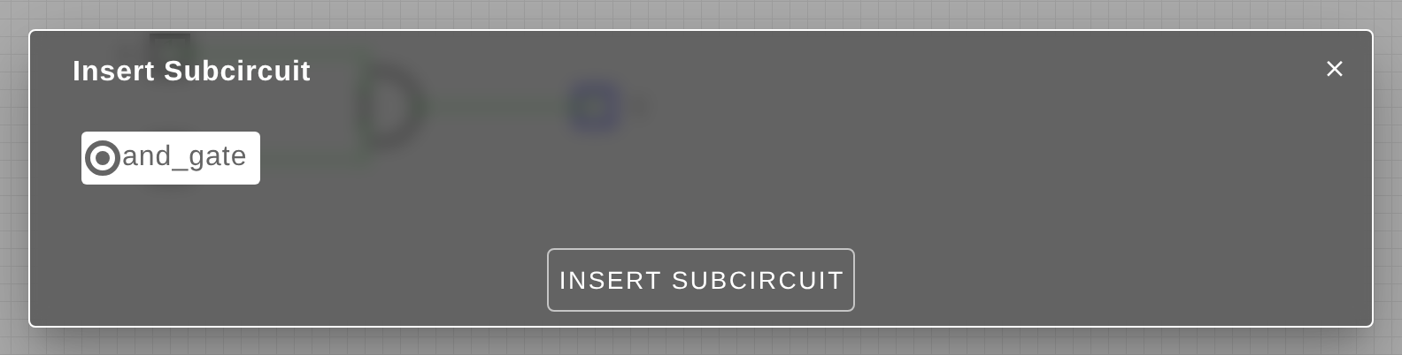 Figure 8.7
 -
The Verilog module will be inserted as box with name of Verilog module and defined input and output ports in the simulator. Refer Figure 8.8.
 Figure 8.8
 -
Verify and Simulate:
- Verify the generated circuit by checking the connections and components.
- Use the simulation tools in LogicPlot to test the functionality of the circuit.
Example
Here is a simple example of Verilog code for a 2-input AND gate:
module ANDGate (
     input A,
     input B,
     output Y
);
assign Y = A & B;
endmodule
After compiling and generating the circuit, you should see a circuit with two inputs (A and B) and one output (Y) representing the AND gate. Add the input and output to the circuit as shown above in figure 8.9 above.

Tips and Warning
- The V2C Generator does not support all the Verilog Constructs, so it might fail to generate circuit for some verilog code.
- Ensure that your Verilog code is well-commented to make it easier to understand and debug.
- Use meaningful names for inputs, outputs, and internal signals and use proper data-types to avoid mistakes.
- Avoid using verilog constructs like file I/O.
By following these steps, you can easily convert Verilog code into a digital circuit using LogicPlot, allowing for better visualization and testing of your hardware designs.